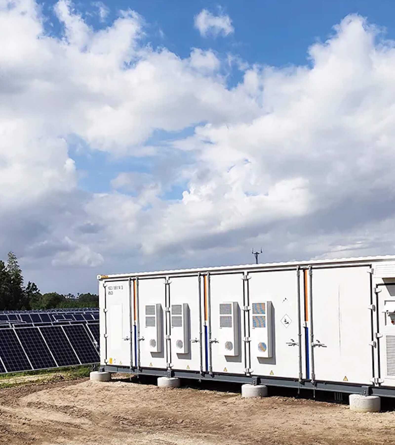
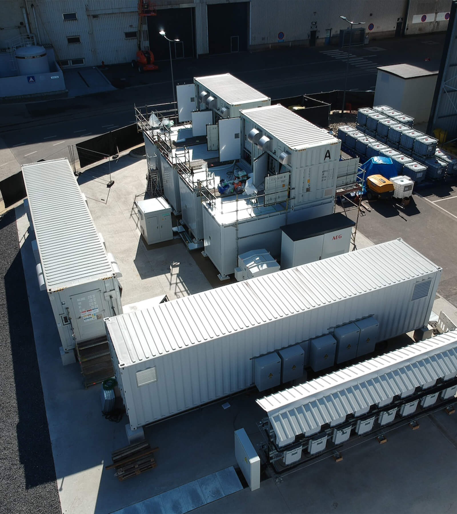
Related Cases


Solution Catalog
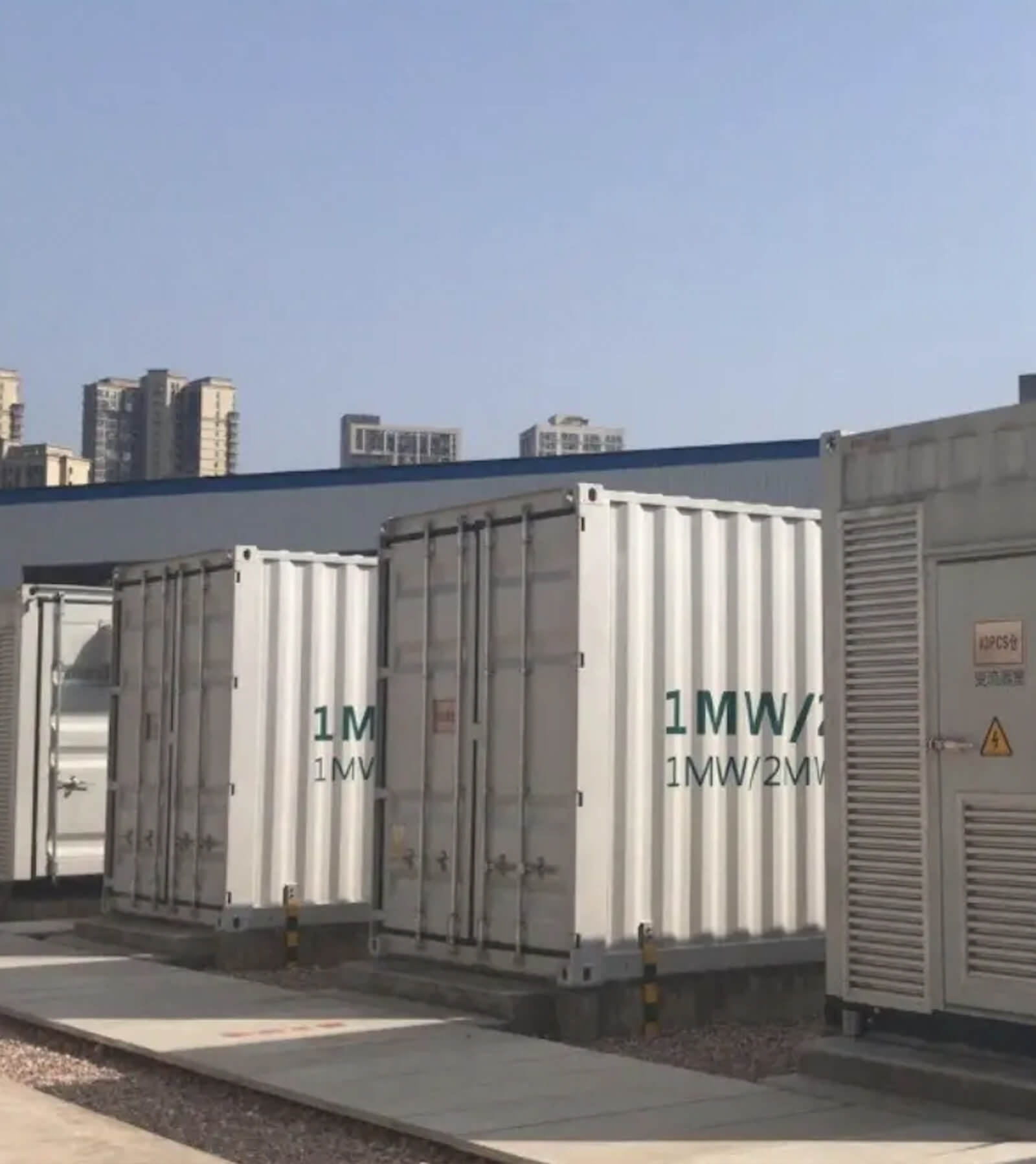
Project Information
According to the requirements, the configuration of the energy storage system is 2MW/6MWh. The specific configurations for using Maxbo container product parameters are as follows.

Battery information
Battery cell specification: LFP battery cell, 3.2V, 280Ah, single capacity is 0.896 kWh.
l Pack specifications: 153.6V/280Ah, cell connection type 1P48S, the capacity of single Pack is 48 x 0.896 = 43.008kWh.
Solution Configuration
7pcs battery pack per battery rack: 7 battery pack serially connected plus 1 High Voltage Box; single capacity of battery rack is 7 x 43.008 = 301.056 kWh.
10 set battery Rack parallel connected in the battery container, total capacity is 10 x 301.056KWh = 3010.56KWh, which are integrated in one 20ft battery container.
There are total 2 Container (3010.56KWh) connect to 2.5MW PCS
The project total capacity of BESS is 6021.12KWh.
Battery System
Battery Cell
Hoypower Battery Storage System rely on LFP chemistry to provide stable, industry leading safety and high-power performance. Each cell is 3.2V 280V, the specification as follows.

Battery Module
Modules are formed by configuring 48pcs LFP cells in series connection. Battery module is connected with a BMU at front. Each rack contains 8 modules and 1 BPU.

Battery Module
Modules are formed by configuring 48pcs LFP cells in series connection. Battery module is connected with a BMU at front. Each rack contains 8 modules and 1 BPU.

BMS
BMS composition
BESS implement a complete, multilevel battery management system (BMS) for system monitoring and control. Each battery management system including:
l Module Battery management unit (BMU)
l Rack Battery Management controlling System (BCU)
l System-level BMS (BAMS)
BMU is designed to detect voltage, temperature, and execute cell balance functions for cells. BCU can manage all module BMS units and detects total voltage, current, and executes protection functions by switching DC-contactor. Finally, a system-level BMS (BAMS) manages rack BMS units and communicates with PCS or EMS. The table below outlines BMS units of the system.


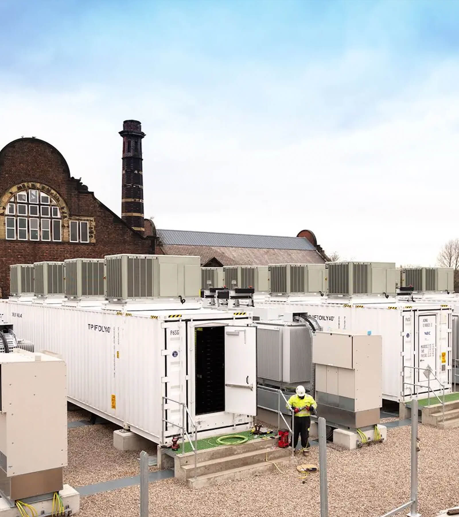
Fire Suppress system
Each container has a separated and independent fire suppression system. According to the working principle of energy storage system and other related standard, Detectors, fire control panel and fire extinguisher are installed in each container. It can constantly monitor the temperature, combustible gas and smoke. When the fire event is detected, control panel will release the fire extinguisher automatically and send a signal to BMS or EMS.
FSS topological graph
Liquid Cooling System
One container is composed of a liquid cooling unit and its liquid cooling pipeline system. The control system automatically controls the work of liquid cooling system according to battery temperature.
Cooling liquid powered by the pump circulate inside the battery modules and take the heat from batteries. The hot liquid will circle back to a heat exchanging tank.
Inside the heat exchange tank, the refrigerant will absorb the heat from hot liquid and cool down the liquid.
Advantage of Liquid Cooling system l Higher cooling capacity
l Better temperature uniformity
l Lower noise emission

Container Layout
1. Chiller
2. Fire extinguisher
3. BCP&Aux cabinet
4. Battery rack